
HG Fiber Series – Fiber-Optic Infrared Thermometer
Fiber-optic infrared thermometers with a small stainless-steel sensing head rated to 125 °C ambient, measuring 300 °C to 2000 °C in high-temperature and high-EMI environments.
Optical fiber carries infrared energy from the sensing head to the electronics box, keeping electronics away from heat and EMI at the measuring point. The box provides 4–20 mA, an alarm relay and on-site emissivity adjustment.
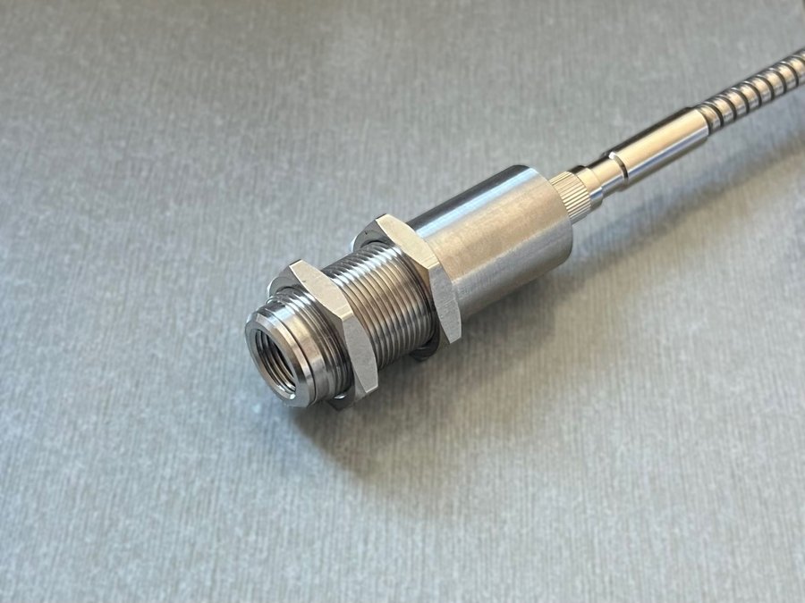
Electronics away from heat and interference
Fiber-optic transmission
Energy is carried by optical fiber, avoiding heat and EMI at the measuring point.
Small stainless head
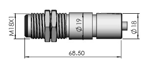
M18×1, 68.5 mm long; ambient −20–125 °C.
Electronics box with LCD
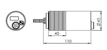
M45×1.5 housing; settings with the button.
4–20 mA and alarm relay
4–20 mA plus a 48 V / 300 mA solid-state relay.
Two wavelengths
IN (1.6 µm, 300–1400 °C) and SI (1 µm, 600–2000 °C).
Ambient temperature alarm
Ambient-temperature alarm set point on the electronics box.
Models and parameters
Two versions: IN (1.6 µm) and SI (1 µm).
| Model | IN | SI |
|---|---|---|
| Spectral range | 1.6 µm | 1 µm |
| Temperature range | 300–1400 °C | 600–2000 °C |
| Optical resolution | 120:1 | 120:1 |
| Response time | 10 ms (95%) | 10 ms (95%) |
| System accuracy | ±0.5% ±2 °C | ±0.5% ±2 °C |
| Repeatability | ±0.3% ±2 °C | ±0.3% ±2 °C |
HG is still sold; figures below follow the series manual (not on the current short coding sample list). Confirm the SKU when ordering.
Measurement
| Emissivity | 0.100–1.099, set with the button |
|---|---|
| Signal processing | Average, peak and valley hold; 4–20 mA range limits |
Electrical
| Power supply | 12–24 VDC |
|---|---|
| Analog output | 4–20 mA |
| Alarm output | Solid-state relay 48 V / 300 mA, isolated |
| Out-of-range signal | Below range: display ---L, output < 3.8 mA · above range: display ---H, output 21–23 mA |
Sensing head / electronics box
| Environmental rating | IP65 / IP65 |
|---|---|
| Ambient operating temp. | −20–125 °C / −10–65 °C |
| Material | Stainless steel / stainless steel |
| Thread · length | M18×1 · 68.5 mm M45×1.5 · 110 mm |
Fiber and cable
| Fiber | 1 m standard |
|---|---|
| Cable | 2.5 m standard |
| Display | LCD on the electronics box |
Lens and spot size
| Standard lens SF | 3.5 mm @ 450 mm (D:S 120:1) |
|---|
Spot examples from the optical diagram: 10 mm at the lens, 3.5 mm at 450 mm, 18 mm at 1000 mm.
Dimension drawings
User cable wiring
| Pin | Wire color | Function |
|---|---|---|
| 1 | Red | Power + |
| 2 | Grey | Relay |
| 4 | White | Relay |
| 5 | Yellow | Current output + |
| 6 | Brown | Current output − |
| 7 | Black | Power − |
| — | Clear | Shield |
User cable 2.5 m standard.
Where HG thermometers are used
High temperature at the sensor
Measuring points too hot for sensor electronics — sensing head rated to 125 °C ambient.
Strong electromagnetic interference
Sites with EMI; 4–20 mA for long runs and interference.
Hard-to-reach or moving targets
Targets that are difficult to approach or are moving.
Frequently asked questions
Why use a fiber-optic thermometer?
How hot can the sensing head get?
What does the output do when the temperature is out of range?
What is in the box
- Sensing head with fiber
- Electronics box
- User cable
Optional accessories
- Mounting hardware for head and electronics box
Need help choosing the right range or optics?
Tell us your application and we will reply within one business day. OEM and custom versions are available — see OEM & Custom.